Those who are now beating up on the new 12VHPWR (although I don’t really like the part either) may generate nice traffic with it, but they simply haven’t recognized the actual problem with the supposedly fire-hazardous and melting connections or cables. Even if certain YouTube celebrities are of a different opinion because they seem to have found a willing object of hate in the 12VHPWR once again: This connection is actually quite safe, even if there are understandable concerns regarding the handling.
However, the “safe” is only valid if e.g. the used supply lines from the power supply with “native” 12VHPWR connector have a good quality and 16AWG lines or at least the used 12VHPWR to 4x 6+2 pin adapter also offers what it promises. Which brings us directly to the real cause of the cases that occurred: It’s the adapter solution exclusively provided by NVIDIA to all board partners, which has fire-dangerous flaws in its inner construction!
Our investigation has now also put NVIDIA on the map, but not officially yet, only in their own board partner circles.
Adapter gate? NVIDIA briefs all board partners this morning and makes damage an absolute boss issue
Let’s first take a quick look at the typical error pattern that occurs when such an adapter triggers a defect, before we start searching for clues inside the accessories distributed by NVIDIA. And before you start beating up the PCIe 5.0 connector, even a layman can see from the error pattern and the load distribution what or where the actual trigger must have been.
As a reminder, I’ll now also briefly show you the block diagram of the special NVIDIA adapter, whereby we are only interested in the upper six yellow connections of the connector including the bridge here. Electrically, all 12V pins are still connected to each other and then also once again to the four feeding wires: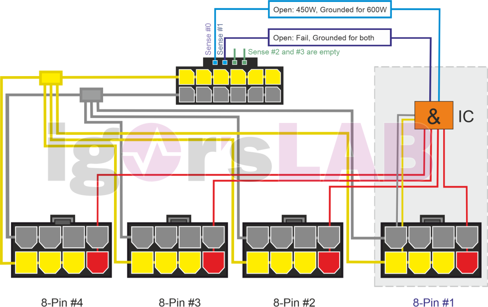
I’m pretty sure that NVIDIA itself doesn’t know or didn’t know exactly what kind of contact party the supplier is having inside the molded connector. Otherwise, this part should not have been approved in this form. When you remove layer after layer, something gradually emerges that you would have been better off not seeing in the first place: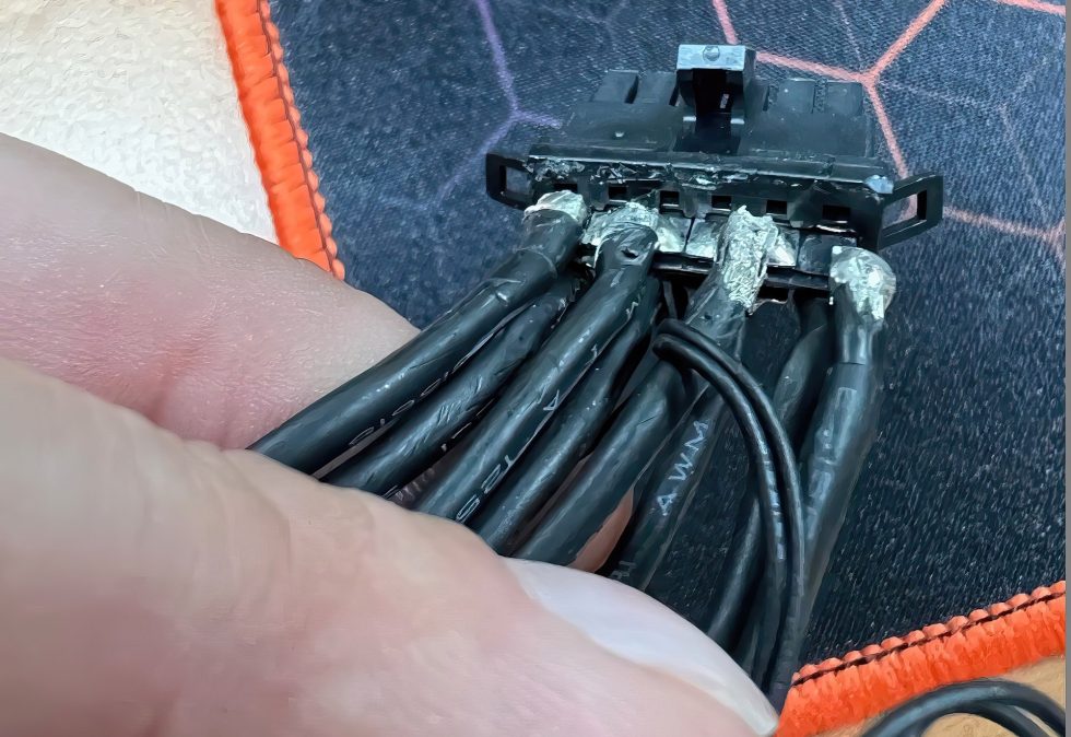
A total of four thick 14AWG wires are distributed over a total of six contacts, with the two outer leads soldered to one pin each and the two middle leads soldered to two pins each. The solder base is a mere 0.2 mm thin copper base with a width of 2 mm per incoming wire, which then results in 4 mm per pair for the middle connections. Soldering one or even two 14AWG wires to it is very sporty. Confucius says succinctly, “What is cast in cannot be seen, and what cannot be seen cannot be broken.”
But just carefully lifting off the enveloping layer causes the thin plate to tear immediately. With which we also see that bending the cables at the connector in the housing can cause such damage. Wobbly contacts or unsafe bridges, as well as increased resistances as a result of such actions are highly dangerous at these current strengths and very quickly lead to exactly the errors that we have already seen above. And you can now also see why especially the two outer contacts of the connector are affected. The scorched socket on the card is then only the consequential damage.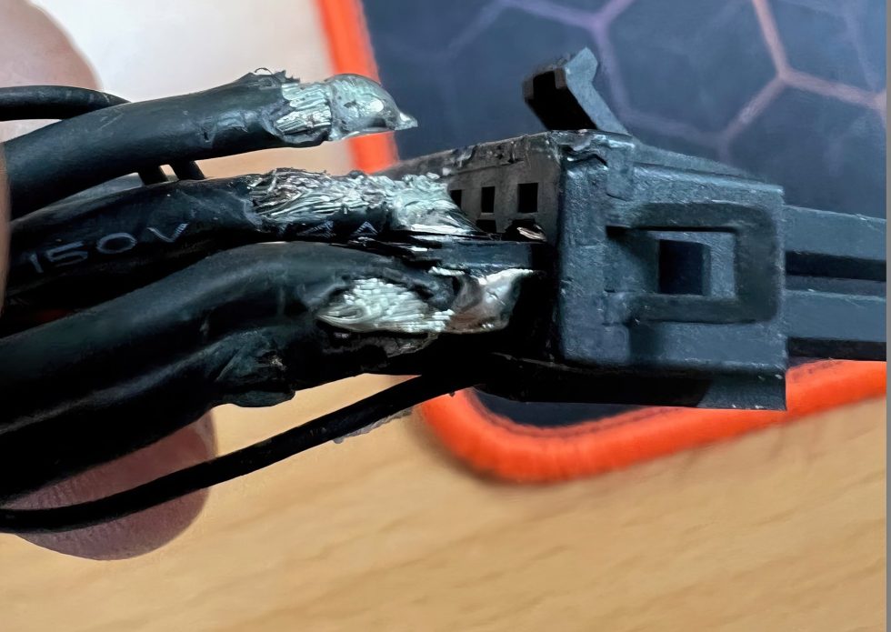
However, you can cut the plug open even further and see what exactly is inside. Because this detail is also highly interesting for the cause research. We see that the contacts in the connector are once again interconnected. If, in the worst case, the outer two wires break off, the entire current in the middle flows through the remaining two wires and is only then distributed in the plug again. But even this “foil” is thin and does not replace a real 14AWG. The fact that this then becomes really hot does not have to be explained separately….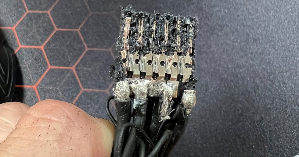
You can like the connection or not, but you also have to stick to the facts and the truth. The native 12VHPWR cables of the better power supplies show that it can be done differently. Incidentally, I also measured the 12VHPWR using resistance sensors and was able to determine absolutely unsuspicious temperatures (picture above). At plenty of 530 watts it was under 60 °C and even the maximum temperature of just under 68 °C I could only prove after an hour with 600 watts in the stress test. But definitely nothing melts there yet!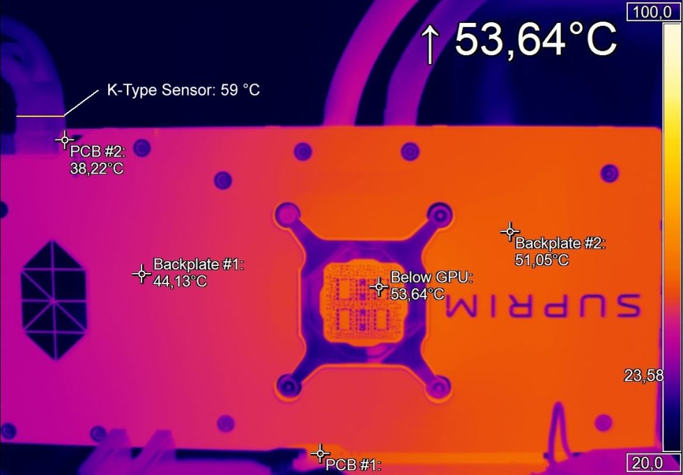
A good example of a functioning connection are, for example, the two 12VHPWR cables of the new be quiet! Dark Power Pro 13, which I still show here as an example. Because there you don’t have to do the balancing act with the voltage bridges, but spend each pin its own 16AWG line. Sure, 12 thick wires in one cable is not that sexy now either, but it is at least an accurate and clean solution. I also snapped these cables right at the connector several times and did much of my testing for the GeForce RTX 4090 as well as the Intel Core i9-13900K in the lab with them on the redundant test system.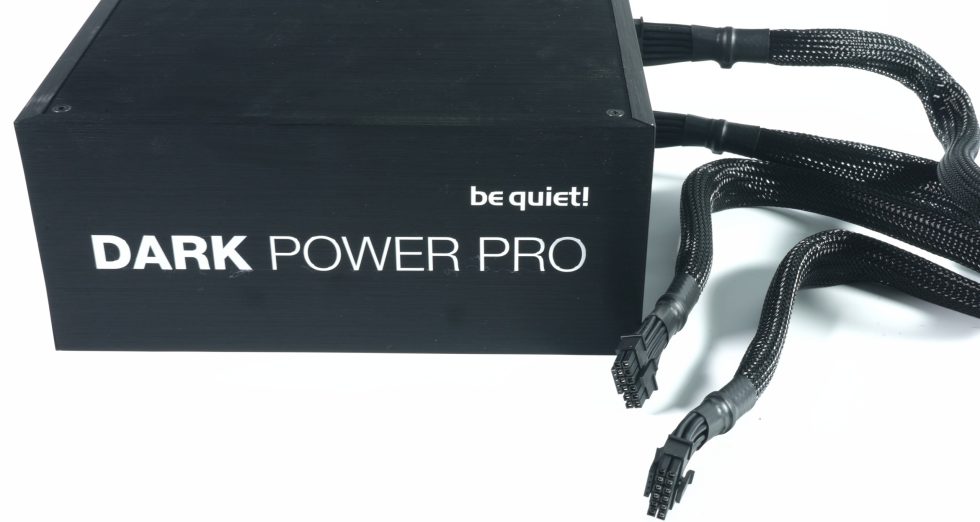
The overall build quality of the included adapter for the GeForce RTX 4090, which is distributed by NVIDIA itself, is extremely poor and the internal construction should never have been approved like this. NVIDIA has to take its own supplier to task here, and replacing the adapters in circulation would actually be the least they could do. I will therefore summarize once again what has struck those involved (myself included) so far:
Actually, I wanted to do something completely different today, but this correction was more important to me. Blanket panic and gloating are really bad advisors here when it comes to introducing new standards. That AMD has not (yet) joined the plug change was shown in my news about one of the upcoming board partners. But if you, like NVIDIA, take such a radical step, then at least the included accessories should work properly over after a little bending and ensure a safe, stable operation of the graphics cards.
This is how the 12VHPWR is done correctly: Crimping instead of soldering and how to supply the GeForce RTX 4090 with power properly
My thanks also go to Christian Rex from be quiet! whose pocket knife was faster than my Dremel.
Source: Own, be quiet!
Zeige alle Kommentare an
Kommentar
Lade neue Kommentare
Mitglied
Vielen Dank für die Untersuchung und Erklärung. So erfährt man wenigstens, was da wirklich abgeht, und nachdem ich selbst Elektroingenieur bin, kann ich die Problematik gut nachvollziehen. Ich finde es auch prima, dass ein deutscher Hersteller von Netzteilen (und anderem) da etwas Besseres zeigen kann und will.
Antwort 4 Likes
Format©
…und muss. Das ist echt gefährlich 😀
Antwort 9 Likes
Veteran
Darauf habe ich schon die ganze Woche gewartet.
Danke für den sachlichen Beitrag.
Antwort 3 Likes
Urgestein
Ich habe es vor vielen Jahren so gelernt, dass Lötstellen in Steckverbindern nur dann eingesetzt werden sollten, wenn eine saubere(!) Zugentlastung vorhanden ist oder man sicher weiß, dass das Kabel nie mechanisch belastet wird. Da letzteres meiner Meinung nach eher selten der fall ist, halte ich das für äußerst gefährlich und muss aus meiner Sicht zwingend ausgetauscht werden.
Ich halte das übrigens für absolute E-Technick Grundlagen.
Antwort 9 Likes
Veteran
Zugentlastung, ein Winkel und ein sauber "verdrahteter/vercrimpter" Stecker wäre hier mein Vorschlag wenn’s in der Firma wäre. Bin kein Stromer aber wenn sich das schon mechanisch löst… Und das man über Klingeldraht (übertreibung) keine 12,5A jagen darf weiß ich auch ^^
Antwort 3 Likes
Veteran
Dabei gibt es so schöne Anleitungen, wie die Stecker zu fertigen sind.
Moderation:
Bitte keine geschützten Dokumente als Upload. Wenn es öffentliche Links gibt, dann gern 🙂
EDIT: OK, Link eingefügt
Antwort 5 Likes
Mitglied
Erhellender Beitrag.
Nur frage ich mich, selbst wenn Nvidia hier "schnell" reagiert (wenn man das überhaupt will), wie viele abgefackelte Buchsen/Stecker oder gar schlimmeres wird es bis dahin wohl geben?
Antwort Gefällt mir
Urgestein
Nein! Ein schrottiger Fackeladapter bei einer 2000 €-Karte. Das wird sich im wahrsten Sinne des Wortes in das kollektive Grafik-Community-Gedächtnis einbrennen. 🔥🚒
Der Fall schmälert mein Vertrauen in Nvidia enorm, beQuiet kann bei mir aber deutlich punkten, da sich die Mitarbeiter dort wohl nicht nur um ihren eigenen Kram scheren.
Antwort 9 Likes
Mitglied
Danke Igor, genau so hab ich mir das schon gedacht. Somit werde ich die Tuffige Asuskarte ganz entspannt mit dem Be Quiet Kabel weiter betreiben.
Für die Zukunft wären evt. Tests von aufkommenden Winkeladapter hilfreich um dort eine weitere Gefahrenquelle auszuschließen.
Antwort 4 Likes
Neuling
Für solche Artikel liebe ich diese Webseite (y)
Antwort 7 Likes
Neuling
Hello, i’ve read this article and I have a question, I bought a remplacement cable from cable mod, is this one safer?
Antwort Gefällt mir
Moderator
That depends on the specs of the cabel. And if the manufacturer was aware / took care of this issue.
I would say, this problem could be even bigger and not only related to the adapter from NVIDIA.
Antwort 1 Like
Veteran
Die Erklärung macht viel Sinn; allerdings fragt man sich dann doch, wer bei NVIDIA für das "Project Management" der Stromversorgung verantwortlich ist. Schon etwas unglaublich, wie ziemlich fundamentale Prinzipien der Elektrotechnik bei der Spezifikation einfach ignoriert wurden.
Antwort 1 Like
Mitglied
Für mich ein Fall von Versäumter Qualitätskontrolle des Zulieferers seitens des Herstellers.
Für die Herstellung/Assemblierung der Stecker gibts klare Vorgaben der Steckerhersteller die hier klar ignoriert wurden.
Bin gespannt wie Nvidia darauf reagiert.
Antwort 2 Likes
Neuling
@Igor Wallossek
Danke für deine Nachforschungen. Das erklärt auch warum das Thema mit dem "nicht Knicken" der Kabeln so gepusht wurde. Was mich noch interessieren würde ist ob es auch ein Problem an den Terminals gibt. Die PCI-SIG hat ja festgestellt das durch knicken der Kabel oder häufigen Stecken die Terminals ausleiern können und somit die Kontaktfläche zwischen den Pins in der Buchse und den Terminals im Stecker geringer wird.
Meinst du dieses Problem ist überwunden oder besteht noch? Falls es nicht mehr besteht sollte nichts gegen gegen ein starkes biegen des Kabels sprechen solange der minimale AWG16 Biegeradius von ~4mm eingehalten wird. (Typischer min. Wert = Faktor 3 des Durchmessers)
Antwort 1 Like
Alle Kommentare lesen unter igor´sLAB Community →
Editor-in-chief and name-giver of igor’sLAB as the content successor of Tom’s Hardware Germany, whose license was returned in June 2019 in order to better meet the qualitative demands of web content and challenges of new media such as YouTube with its own channel.
Computer nerd since 1983, audio freak since 1979 and pretty much open to anything with a plug or battery for over 50 years.
Follow Igor:
YouTube Facebook Instagram Twitter